Thursday, January 2, 2020

Is 2-2-V-1 Piece of the Sydney Island C-47 Wreck? Update #3

The latest notable response to Tom Palshaw's report is a post on the TIGHAR discussion forum by Ric Gillespie reporting new rivet line spacing measurements for 2-2-V-1 [1]. According to Gillespie:

 “The differences, while not huge (see “Actual v template”.jpg ) are significant when measuring precise alignment with the pattern on the C-47 wing. Palshaw’s template appears to fit the C-47B wing but it does not accurately reflect the artifact.

The ‘Actual v. template’ figure (see below) is Gillespie’s markup of a photo in the Palshaw report showing a paper template of 2-2-V-1 laid over the New England Air Museum (NEAM)  C-47 wing. The lines on the template were made by Tom Palshaw to indicate 2-2-V-1’s rivet line spacings based on earlier TIGHAR data. The numbers in yellow were added by Ric Gillespie to indicate his new rivet line spacings. I’ve further marked up the photo with the numbers in blue to correct errors in two of Gillespie’s numbers.

Gillespie's new rivet line spacing measurements superimposed on Tom Palshaw's  2-2-V-1 template.
The differences between the new rivet line spacings and those in Tom Palshaw’s template are small, as Gillespie notes. Do these differences matter with regard to the question of whether 2-2-V-1’s rivet lines match those of the NEAM C-47 wing? Tom’s template was a stand-in for 2-2-V-1, which he didn’t have access to when he wrote his report. Rather than concerning ourselves with Tom’s template, let’s consider how well the thing itself, 2-2-V-1, matches the wing. The photo below is a screen shot from the YouTube video of Gillespie and Palshaw comparing 2-2-V-1 to the NEAM C-47 wing in 2017 [2]. At the edge of 2-2-V-1 closest to the camera 2-2-V-1’s rivet hole lines appear align well with those on the underlying C-47 wing. Gillespie’s new measurements don’t appear to disqualify the NEAM C-47 wing as a match for 2-2-V-1, at least at the side closest to the camera. The YouTube video does not provide as good a view of the far end of 2-2-V-1, but neither Gillespie or Palshaw say in the video that the rivet line spacings of the C-47 wing and 2-2-V-1 don’t match.

Direct comparison of 2-2-V-1 to the NEAM C-47 wing

Further along in the same TIGHAR forum post in which Ric Gillespie reports his new rivet line spacing measurements, he writes:

For the best possible comparison to the C-47A that crashed on Sydney Island, we need to come as close as we can to apples-to-apples. We need to do a detailed examination and measurement of the relevant section on the wing of the closest surviving C-47A by tail number.  We will be doing that later this winter.

While it would be interesting to see how well 2-2-V-1 matches the wings of other C-47s, surely a careful examination of the NEAM C-47 wing should take precedence over comparisons to other C-47s. All information available so far indicates that the NEAM C-47 wing is a close match to 2-2-V-1. The doubts Gillespie raised in the YouTube video were addressed in the Palshaw report, and since then Tom has found additional matching features, as discussed in my earlier posts. TIGHAR should collaborate with Tom Palshaw to carefully compare 2-2-V-1 to the NEAM C-47 wing to determine just how well they match. Ric Gillespie has written that “TIGHAR is an educational foundation and the Earhart mystery is a perfect vehicle for exploring, demonstrating, and teaching the scientific method of inquiry” [3]. The scientific method of inquiry most definitely is not about ignoring observations that suggest a favored hypothesis is wrong.

If we are to believe that 2-2-V-1 came from the Sydney Island C-47 wreck, it is reasonable to expect proof that 2-2-V-1 matches some part of a C-47.  Likewise, if we are to believe that 2-2-V-1 is a piece of Amelia Earhart’s Lockheed Electra it is reasonable to expect that TIGHAR demonstrate that  2-2-V-1 corresponds to a source location on Earhart’s Electra. According to TIGHAR, that source location is the ‘Miami Patch’, an aluminum alloy sheet that was attached to Earhart’s Electra in Miami to cover a window early on the voyage on which she disappeared. In the photo below taken shortly after it was installed, the shiny new Miami Patch stands out from the more weathered fuselage to which it had been attached.

The newly-installed window patch. Miami, June 1937.

A basic requirement for 2-2-V-1 to be a piece of the Miami Patch is that it must be smaller than the Miami Patch. This is necessarily true because nowhere on 2-2-V-1 is there an original manufactured edge; 2-2-V-1 was clearly torn away from a larger piece of aircraft skin. TIGHAR has stated that 2-2-V-1 fits within the perimeter of the Miami Patch but as far as I know it has never published a photo demonstrating this to be the case. One place where TIGHAR states that 2-2-V-1 fits within perimeter of the Miami Patch is in TIGHAR Research Bulletin #72 [4]. A section titled ‘Do the dimensions of the artifact fit within the dimensions of the patch?’ states:

To answer that question required accurate scaling and the removal of camera-induced distortion from the Miami Herald photo and a photo of 2-2-V-1 pressed down to allow measurement of its full size.  The edges of the patch were straight and riveted, while the borders of the artifact are all failed edges, with one side showing evidence of a line of staggered rivets. If the artifact is a broken-out portion of the patch it must fit within the dimensions of the patch. TIGHAR forensic imaging scientist Jeff Glickman was able to remove the distortion and accurately scale and overlay the photos. The artifact fits nicely within the patch.

The accompanying image of the overlay, see below, does indeed depict 2-2-V-1 as nicely fitting within the boundaries of the Miami Patch. Given 2-2-V-1’s size, the overlay suggests that 2-2-V-1 is several inches smaller than the Miami Patch both vertically and horizontally.


But this overlay must be in error, because actual photos of 2-2-V-1 held close to surviving Lockheed Model 10 Electras show that if 2-2-V-1 fits within the Miami Patch’s boundaries at all, it does so with very little room to spare. TIGHAR Research Bulletin #73 [5] reports the results of an examination of an Electra undergoing restoration in Wichita, Kansas. The report includes the photo below of 2-2-V-1 held close to the exterior of the Wichita Electra’s fuselage, with the perimeter of the Miami Patch outlined somewhat inaccurately with yellow adhesive measuring tape. 2-2-V-1 does not appear to fit within the marked boundaries of the Miami Patch. The ‘Tab’ feature at the bottom edge of 2-2-V-1 extends below the lower boundary of the Miami Patch, which in this photo corresponds to the upper edge of the yellow tape. 2-2-V-1 also overlaps the yellow tape that marks the forward perimeter of the Miami Patch, which in this photo is placed too far forward. As discussed in TIGHAR Research Bulletin #73 itself, the forward edge of the patch had to be tailward of where it appears in the photo [6]. 2-2-V-1 fits within the upper perimeter of the patch, but perhaps only because as 2-2-V-1 is held in this photo it bulges outward, which lessens any vertical mismatch between it and the patch. Remember that since 2-2-V-1 is a remnant of a larger piece of metal, it must not only fit within the perimeter of the patch, it must do so with room to spare. TIGHAR Research Bulletin #73 notes the lack of fit apparent in this photo and explains it as being an effect of perspective, i.e., 2-2-V-1 appears to be larger relative to the fuselage than it really is because it’s slightly closer to the camera. Why this report did not include a photo of 2-2-V-1 pressed against the side of the Wichita Electra to clearly show how well it fits within the required perimeter is a mystery; surely a thin sheet of transparent plastic could have been placed between fuselage and 2-2-V-1 to prevent cosmetic damage to the surface of the airplane if that was a concern.

2-2-V-1 compared to the Miami patch perimeter, Wichita.

If TIGHAR has a photo from the Wichita exercise that properly compares 2-2-V-1 to the Miami Patch’s perimeter, it should publish that photo to support its claim that 2-2-V-1 is a piece of the Miami Patch. If TIGHAR does not have such a photo, it is all the more reason to return to NEAM. NEAM has a Lockheed Model 10 Electra in its collection, so in addition to documenting how well 2-2-V-1 matches the NEAM C-47 wing, TIGHAR can document how well 2-2-V-1 fits within the boundaries of the Miami Patch.

Some time ago Ric Gillespie posted a photo on the TIGHAR Forum similar in composition to the Wichita photo, but using the NEAM Electra's fuselage as the backdrop and the patch perimeter marked with clear adhesive tape.  That photo (see below) shares some of the Wichita photo’s problems, e.g., the forward perimeter is placed too far forward and 2-2-V-1 bulges outward. Additionally, 2-2-V-1 is held at an unlikely angle with respect to the Electra’s fuselage; the lowest rivet line would not span the width of the patch at the angle it makes with the lower boundary of the patch. Gillespie notes some of these problems, but his assessment was nevertheless that "It's not a great photo and the placement is a bit too high and a tad too far forward on the airplane but, as you can see, it all works". But it doesn't all work. 2-2-V-1 extends beyond the upper and lower perimeter of the patch even though its outward bulge reduces the extent of the overlap, and since the forward perimeter is too far forward, it is not clear that 2-2-V-1 is fits horizontally within the Miami Patch's boundaries. Once again I note that 2-2-V-1 must fit with room to spare since it is a fragment of a larger piece of metal.

2-2-V-1 compared to the Miami Patch perimeter, New England Air Museum

TIGHAR claims that 2-2-V-1 is small enough to be a piece of the Miami Patch, but it hasn’t provided clear photographic proof that this is true. It should take less than an hour at NEAM to properly compose a comparison photo that would provide this needed proof. The four borders of the patch perimeter would need to be properly positioned on the fuselage and 2-2-V-1 would need to be pressed against the NEAM Electra's fuselage to minimize bulges and to eliminate effects of perspective.

Comments, corrections, additional relevant facts, differing viewpoints, etc., are always welcome.  Send to gardnersghost@gmail.com
+++
References

[1] https://tighar.org/smf/index.php/topic,2074.msg43506.html#msg43506
[2]  https://www.youtube.com/watch?v=GlVLyOfsZ3c&t=101s
[3] https://tighar.org/smf/index.php/topic,1999.msg42342.html#msg42342
[4] https://tighar.org/Projects/Earhart/Archives/Research/Bulletins/72_SmokingGun/72_Smoking_Gun.html
[5] https://tighar.org/Projects/Earhart/Archives/Research/Bulletins/73_StepbyStep/73_Step_by_Step.html
[6] In the Wichita photo, the forwaed perimeter coincides with a row of staggered rivets at what is referred to as 'Station 293 5/8'.  TIGHAR Research Bulletin #73 states: "The frame could not be riveted directly to the underlying structure at Sta. 293 5/8 because of the thick lavatory bulkhead on the interior (no way to buck the rivets), so new underlying structure was added just aft of Sta. 293 5/8 to provide something to rivet the frame to".

Wednesday, December 11, 2019

Is 2-2-V-1 Piece of the Sydney Island C-47 Wreck? Update #2

Tom Palshaw’s report that TIGHAR Artifact 2-2-V-1 matches a section of the upper wing of a C-47 transport plane has elicited some interesting responses at TIGHAR’s discussion forum. A TIGHAR member stated that Tom had made a good case that a C-47 wing was the source of TIGHAR artifact 2-2-V-1 but suggested that Tom should further document his findings. He also suggested that Tom provide photographic evidence of C-47 wing features, such as the spacing between rows of rivets and the rivet pitch, i.e., the distance between rivets in each row. This led Ric Gillespie to make a post on the forum, the key points of which I’ll quote below:

If 2-2-V-1 is from the wing of a C-47, all aspects of the artifact must match. Beyond row spacing and pitch, the following must also match:

• Rivet size (shaft diameter):
The rivet on 2-2-V-1 has a shaft diameter of 3/32 inch - source NTSB Laboratory.

• Rivet length (shaft length):
The rivet on 2-2-V-1 has a shaft length of 3/16 inch - source NTSB Laboratory.

• Rivet material:
The rivet on 2-2-V-1 has a dimple in the center of the head, signifying it is made of A17ST alloy - source "Aircraft Maintenance and Repair" Northrop Aeronautical Institute, 1955. See attached PDF of rivet coding.

• Rivet head type:
The rivet on 2-2-V-1 is a "brazier" head. A brazier head rivet has a low profile, minimizing drag. There are two kinds of brazier head rivets,  the "full brazier head" and the "modified brazier head".  As early as 1930 and as late as 1941and possibly later, the "modified brazier head" was known as the "mushroom head."  The rivet on 2-2-V-1 is what is now known as a "full brazier head" rivet. Lockheed Electras had dimpled "full brazier head rivets" identical to the rivet on 2-2-V-1.  See photo below.


• Sheet thickness
The 2-2-V-1 sheet has a thickness of 0.032" - Source NTSB Laboratory


Tom saw these comments and in response wrote a detailed explanation of how various measurements he made were done. This additional information now appears in Tom’s report as Appendix II.

In this post, I’ll provide what I hope is a summary of Tom's Appendix II that will be helpful to layman like me out there who are following the 2-2-V-1 story. I’ll also provide additional information on how 2-2-V-1 appears to match the NEAM C-47 wing that Tom only became aware of after his report was published online.

The first bullet item is about rivet shaft diameter.  During Gillespie and Palshaw’s joint examination of the NEAM C-47 wing, Ric Gillespie questioned whether certain rivets were -4 rivets rather than -3 rivets. One of the main points Tom makes in his report is that the rivets in question are indeed -3 rivets. Appendix II of Tom’s report explains how  this was determined. Tom removed a rivet from the C-47 wing and inserted a drill that matched the rivet hole. This was a number 40 drill, the recommended drill size for -3 rivet holes. The matching drill for a -4 rivet hole is a number 30 drill, which does not fit into a -3 rivet hole. Tom provided a table from the Canadair Challenger Structural Repair Manual (1981), 51-42-11, page 6, figure 4, reproduced below, showing the correspondence between drill numbers and rivet hole sizes. Tom verified the -5 rivets on the C-47 wing using this same drill matching method.


Interested readers can check the photo below to see where Tom removed -3 rand -5 rivet removed from the C-47 wing to verify their sizes.

The second bullet item about rivet length states: “The rivet on 2-2-V-1 has a shaft length of 3/16 inch - source NTSB Laboratory.” I checked the NTSB report on TIGHAR’s web site [1] but see nothing there about rivet shaft length, so I will set this bullet item aside.

The third bullet item is about rivet material. Gillespie states:

“The rivet on 2-2-V-1 has a dimple in the center of the head, signifying it is made of A17ST alloy”

The photos included in Tom’s report aren’t sharp enough to show whether the rivet heads have dimples, so I asked Tom about the rivet heads, and he confirmed that they do in fact have dimples. He sent me the photo below of -3 rivets on the C-47 wing that demonstrates this to be the case. The ruler laid alongside the -3 rivets makes clear that the 1 inch pitch of the -3 rivets. Thus, in terms of the material type and rivet pitch the NEAM C-47 wing matches TIGHAR artifact 2-2-V-1.


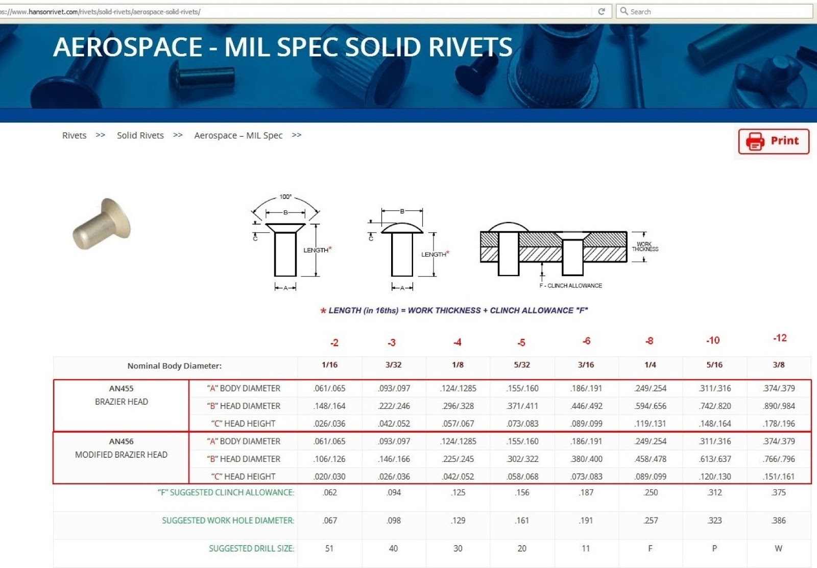
The fourth bullet item about rivet head type states that the one -3 rivet still attached to 2-2-V-1 is a brazier head rivet. The Matching Characteristics section of Tom’s report states that the  C-47 wing -3 rivets are also brazier head rivets. Tom confirmed in an email exchange with me that that the C-47 wing -3 rivets are brazier head rivets, not modified brazier head rivets.  The table below indicates that -3 brazier head rivets and -3 modified brazier head rivets have quite different head diameters and so can be readily distinguished from one another based on their size. Readers can check the photo above against the table below to confirm that diameter of the -3 rivet heads on the C-47 wing are correct for -3 brazier head rivets, not modified brazier head rivets.


Gillespie’s fifth bullet item concerns sheet thickness.  The ALCLAD sheet that 2-2-V-1 is made of is 0.032 inches thick. The ‘What on Artifact 2-2-V-1 Matches the Wing of a C-47B?’ section of Tom’s report states that the thickness of the NEAM C-47 wing in the area of interest is also .032 inches. The excerpt below from Appendix II of Tom’s report states:

To determine the grip length it was necessary to first measure the skin thickness. This was done by using a micrometer at the edge of the skin. To measure the grip length a "calibrated" cleco was used to compare a known stack up of aluminum to that of the wing. The result was a skin thickness of 0.032" and a stringer thickness of 0.060". This is similar to the NTSB Report.

Some of this is a little over the head of a layman like me, but what’s clear is that Tom determined the 0.032 inch skin thickness of the NEAM C-47 wing skin in the area of interest by using a micrometer to measure the skin edge.  Note also that in the above excerpt Tom points out another matching point between the C-47 wing and 2-2-V-1: in both cases, the underlying stringer the skin is attached to was 0.060 inches thick.

That is my layman’s summary of Tom Palshaw’s Appendix II.

I also mentioned that after Tom’s report was published he realized that there was yet another way in which the C-47 wing and 2-2-V-1 match. This new information has to do with 2-2-V-1’s ‘Tab’ feature. A line of –5 rivet holes runs along one edge of 2-2-V-1, and a ‘Tab’ of material juts out from that same edge (see photos below).  At the far edge of the ‘Tab’ are what appear to be partial holes of another line of rivets. I sent Tom a close-up photo of the Tab with measuring tape laid over it (see photos below) that indicates a 1 5/16 inch spacing between 2-2-V-1’s line of -5 rivets and the rivet line at the far edge of the Tab. On the NEAM C-47 wing the line of -5 rivets that corresponds to the -5 rivet line on 2-2-v-1 has a line of -6 rivets running adjacent to it, separated by 1 5/16 inches (see photo below). Thus, the spacing between these two rivet lines on the C-47 wing matches the spacing of the rivet lines seen on 2-2-V-1's Tab. Tom thinks the partial rivet holes on the Tab’s edge are for size -6 rivets, but none of the holes is complete, so this is unclear.

2-2-V-1. The Tab is at the lower edge. The line of -5 rivet holes runs across the lower edge of 2-2-V1 and through the Tab

Spacing between rivet hole lines on the Tab

Spacing between -5 and -6 rivet hole lines on the NEAM C-47


Ric Gillespie's remark that the C-47 wing is "not even close" to a match for 2-2-V-1, as he put it, just does not seem to hold up, given what Tom Palshaw has reported.  If clearer documentation of the C-47 wing's features are needed, I think Ric Gillespie knows how to obtain it.

Comments, corrections, additional relevant facts, differing viewpoints, etc., are always welcome.  Send to gardnersghost@gmail.com
+++
References
[1] https://tighar.org/Projects/Earhart/Archives/Documents/NTSB_Report/ntsbreport.html

Wednesday, December 4, 2019

Is 2-2-V-1 a Piece of the Sydney Island C-47 Wreck? An Update.


Two days ago I published a short post on Tom Palshaw’s report matching TIGHAR artifact 2-2-V-1 to the upper section of the wing of a C-47 in storage at the New England Air Museum (NEAM). Ric Gillespie had recently stated on the TIGHAR Forum that he had examined the NEAM C-47 wing and found it to be “not even close” to a match to 2-2-V-1, but he offered no specifics to back up this assessment.  I thought Tom had made a good case for 2-2-V-1 being a scavenged piece of the Sydney C-47 worthy of a more substantive response than Ric Gillespie had given it.

A TIGHAR forum member alerted Ric Gillespie to Tom’s online report, and possibly for this reason Gillespie posted a video of his examination of the NEAM C-47 wing back in 2017 on TIGHAR’s YouTube channel [1]. Tom participated in this examination, and the photo below shows Tom and Ric standing alongside the subject C-47 wing at the start of their joint examination.


The photo below shows 2-2-V-1 laid over the C-47 wing at the location of interest. The spacing between five rivet hole lines on the side of 2-2-V-1 closest to the camera matches the rivet line spacing of the underlying C-47 wing quite well. There isn’t a good view in the video showing how closely the rivet hole lines match at other side of 2-2-V-1, but I think it is pretty clear that the alignment is close on that side as well, because nowhere in the video does Ric or Tom say that 2-2-V-1’s rivet line spacings don’t match those of the C-47 wing. So in terms of spacing of rivet hole lines, 2-2-V-1 seems to match up well with Tom’s candidate C-47 wing.


So in what ways might 2-2-V-1 not match a C-47 wing, if not rivet line spacing? Ric offers three primary objections to Tom’s proposed match, which if I understand them correctly are as follows:

  • One line of rivets on the C-47 wing are the wrong sized rivets, i.e., -4 rivets rather than -3 rivets
  • The line of -5 rivets of the C-47 lacks the irregular spacing between 2-2-V-1’s row of -5 rivet holes (these are the rivet holes along the right edge of 2-2-V-1 in the above photo
  • A straight portion of what is the far edge of 2-2-V-1 in the above photo is thought to represent a fatigue failure caused by repetitive bending against a straight object. Ric argues this straight object must an underlying structural component, but no such structural component exists where Ric argues it would need to be.
In the TIGHAR YouTube video, Tom appears to accept Ric’s three objections. However in the days after Ric’s visit, Tom examined the C-47 wing more closely and found reasons to think that he had been too hasty in accepting Ric’s objections:
  • Tom found that the line of rivets Ric thought to be -4 rivets (too big) were actually -3 rivets (matching 2-2-V-1)
  • Tom found that there were irregularities in spacing between -5 rivets, just as on 2-2-V-1
  • In Tom’s opinion, Ric’s hypothesis for the formation 2-2-V-1 straight-edge failure feature was not the only way the straight edge could have been created. Tom suggested instead that “2-2-V-1 was originally larger when removed from the source aircraft. A piece could then have been removed later by placing the artifact between two straight angles and flexed to failure
All of these points were made by Tom in an email Tom sent Ric Gillespie a few days after the NEAM visit in 2017. That email differs only in small ways from Tom’s online report. My understanding is that Ric Gillespie has never responded to Tom’s email.

All this makes it very hard for me to understand how Ric Gillespie could have recently said that the C-47 wing he and Tom examined is not even close to a match for 2-2-V-1. I can only conclude from the information available to me that Tom Palshaw has found a plausible candidate source for 2-2-V-1, and not only because of the many ways in which the features match, but also because the people of Gardner Island used scavenged aluminum from the Sydney Island C-47 wreck for making handicrafts [2].

I suspect this post will be followed by several more update posts.

Comments, corrections, additional relevant facts, differing viewpoints, etc., are always welcome.  Send to gardnersghost@gmail.com
++++
References

[1] https://www.youtube.com/watch?v=GlVLyOfsZ3c

[2] Earhart Research Bulletin #7, 7/26/98. Accessible at:
https://tighar.org/Projects/Earhart/Archives/Research/Bulletins/07_Sydneycrash/07_Sydneycrash.html

Sunday, November 24, 2019

Is 2-2-V-1 a Piece of the Sydney Island C-47 Wreck?

Since 1992 TIGHAR has argued that piece of aluminum sheet it refers to as artifact 2-2-V-1 found during a TIGHAR expedition to Nikumaroro is a piece of Amelia Earhart's Lockheed Model 10 Electra [1]. TIGHAR's initial case for 2-2-V-1 was that it was a piece of the underbelly of the Electra was quickly debunked. But Ric Gillepsie, TIGHAR's leader, is nothing if not persistent, and so TIGHAR continued over the years to try to find a way to fit 2-2-V-1 onto Earhart's Electra. Many of the key points Gillespie has put forward over the years for 2-2-V-1 being a piece of the Electra have turned out to indicate the opposite but Gillespie simply continues to march forward, steadfastly ignoring or downplaying evidence that goes against his preferred conclusion.

The long history of TIGHAR's claims about 2-2-V-1 is something that I've been wanting to  post about because I think it illustrates problems that arise all too often with TIGHAR's promotion of the Nikumaroro Hypothesis (Gillespie would of course say that he is testing the Nikumaroro Hypothesis, not promoting it, but come on...).  Anyone who scrolls back through my blog posts can see that I'm not exactly a prolific generator of new material. So while my epic blog post series on 2-2-V-1 awaits fruition I'd like to point readers to a report by Tom Palshaw, who works on aircraft restoration projects at the New England Air Museum in Connecticut.  It is pretty clear that 2-2-V-1 isn't from Earhart's Electra, but then what airplane is it from? Tom has suggested a possible answer: he has found that rivet line spacings, rivet types, and aluminum ‘skin’ thickness of artifact 2-2-V-1 match a section of the upper  wing of a C-47 in NEAM's collection.  C-47s were workhorse U.S. military transport planes during World War Two, and significantly, a C-47 crashed on Sydney Island, another island in the Phoenix Island group, during the war [2].  According to TIGHAR, pieces of that  C-47 were brought to Nikumaroro for use by local inhabitants in making items such as combs.

I helped Tom create an online a report of his findings, which can be found here.

I'm certainly no expert on aircraft manufacture but it seems to me that Tom Palshaw has made a good case that 2-2-V-1 is a piece of aluminum recovered from the Sydney Island crash. It also seems to me that the substance of Tom's findings should be better known by TIGHAR's followers than they probably are. Tom informed Ric Gillespie of this putative match back in 2017, but for two years TIGHAR said nothing about Tom's findings on the TIGHAR discussion forum or its Facebook page.  That silence was only broken this summer when Gillespie made the following tersely worded post on TIGHAR forum [3]:

"On July 16, 2017 I inspected the portion of the DC-3/C-47 wing section at the New England Air Museum alleged to resemble Artifact 2-2-V-1. At the time the wing section was out behind the museum, stored outdoors with various other bits and piece of aircraft. There was no way to check the thickness of the skin but, although there were some general similarities in rivet pattern, the rivet type, rivet pitch, and spacing between rivet lines did not match the artifact. Not even close. TIGHAR videographer Mark Smith recorded the investigation."

Gillespie doesn't provide TIGHAR forum members with Tom Palshaw's side of the story although by this time Gillespie had long since received by email from Tom an analysis that is not much different from the online report I've linked to above. Gillespie could simply have quoted from Tom's email or provided a summary of Tom's key points in his post.  Tom sent Ric a photo showing how a template of 2-2-V-1 matches up with the NEAM C-47 wing (see below), and the match looks pretty good to me, certainly close enough to wonder why Gillespie could have made his 'not even close' comment.


Given all the ink that has been spilled about 2-2-V-1 by Ric Gillespie, it strikes me that Tom Palshaw's findings deserve a serious reply from Gillespie. It could be that Gillespie is correct that C-47 wing is 'not even close', but it isn't enough for Gillespie to simply say it, he needs to explain why that is so. 


+++
References
[1] See TIGHAR TRACKS, Vol. 8 No. 1/2, article titled 'WE DID IT'. Accessible at:  https://tighar.org/Publications/TTracks/1992Vol_8/0801_2.pdf
[2] See TIGHAR Earhart Research Bulletin #7, 7/26/98. Accessible at:
https://tighar.org/Projects/Earhart/Archives/Research/Bulletins/07_Sydneycrash/07_Sydneycrash.html
[3] See TIGHAR forum thread titled 'RE: 2-2-V-1 Wing Panel Comparisons', post #2. Accessible at:  https://tighar.org/smf/index.php/topic,2074.msg43099.html#msg43099

Note: I originally learned about Tom Palshaw's findings from a post made on the Aviation Mysteries forum. I would link to that post here if I could find it. The post was made long ago and is now buried somewhere deep within the discussion threads there.


Friday, October 26, 2018

The Origin of the Nikumaroro Sextant Box

When I started this blog I knew that I’d be writing about the origin of the Nikumaroro sextant box, but I didn’t think it would take me so long to get to it.  A brief review of what the Nikumaroro sextant box is and how it fits into the matter of the disappearance of Amelia Earhart’s is in order before I get to the main point of this post.

Amelia and her navigator, Fred Noonan, disappeared while attempting to fly across the Pacific Ocean in a Model 10E Lockheed Electra.  They took off from Lae, New Guinea on the morning of July 2, 1937, heading for tiny Howland Island, some 2500 miles away, and were never seen again. The group TIGHAR promotes the Nikumaroro Hypothesis — that having failed to find Howland, Earhart and Noonan landed the Electra on Gardner Island, now known as Nikumaroro, a then-uninhabited atoll located 400 miles to the southeast of Howland.  The Nikumaroro Hypothesis further supposes that a few days after Amelia landed the Electra on Nikumaroro’s fringing coral reef the plane was washed into the ocean and that Amelia and Fred died on Nikumaroro in the following weeks or months.

In support of the Nikumaroro Hypothesis, TIGHAR points to the story of the discovery of the remains of a castaway on Nikumaroro in 1940, not long after the island was settled by colonists from the British Gilbert and Ellice Islands Colony.  The settlement of Nikumaroro was carried out under the supervision of Gerald Gallagher, a British colonial official, in what was one of the final acts of expansion of the British Empire.  In September, 1940, Gerald Gallagher informed his superiors that the partial skeleton of a castaway had been found earlier in the year by a colonist work party, presumably while they were clearing vegetation for the planting of coconut palm trees.

Gallagher reported that searches of the vicinity of the castaway’s remains turned up several items, including a fragment of what he took to be a woman’s shoe and an empty sextant box marked with two four-digit serial numbers — 3500 and 1542.  Gallagher suggested to his superiors that the castaway might have been Amelia Earhart.  Gallagher’s superiors took this suggestion seriously and had the bones and items found near them sent to them for further analysis.  A doctor named David W. Hoodless, who taught at the Central Medical School in Fiji, examined the bones and concluded that the castaway had been a short, stocky male.  The sextant box was examined by Harold Gatty, a world-famous pioneer of air navigation who happened to be in Fiji. It is clear from Gatty’s remarks that he understood that he was being asked whether the sextant box could have come from Earhart’s Electra.  Gatty’s opinion was that the sextant box could not have been that of a navigation sextant used in modern aviation — ‘modern’ here meaning the late 1930s.  With the possibility of the castaway being Amelia Earhart ruled out, there was no further interest in determining the identity of the castaway.

In 1998 TIGHAR had Dr. Richard Jantz, a forensic anthropologist at the University of Tennessee, reanalyze the bones measurements made by Doctor Hoodless during his 1940 examination of the castaway’s bones (the castaway’s bones and the other items found nearby have long since disappeared).  Jantz cautiously concluded that the bones were ‘more likely female than male’ and were ‘more likely white than Polynesian or Pacific Islander’ [1].  This wasn’t exactly a resounding affirmation of the Nikumaroro Hypothesis, but TIGHAR made much of Jantz’s findings, sometimes neglecting to indicate the degree of uncertainty in Jantz’s conclusion.  In 2015 Pamela Cross of the University of Bradford and Richard Wright of the University of Sydney published a paper disputing Jantz’s conclusions, arguing that there was no reason to disbelieve Dr. Hoodless’s original conclusion that the castaway was a man [2].  In response to the Wright and Cross paper, Jantz conducted a new re-analysis of Dr. Hoodless’s notes, and this year published a paper that essentially concluding that there is a high probability that the castaway was Amelia Earhart [3].  I’m not a forensic anthropologist and the subject of this post is the Nikumaroro sextant box, so I will leave the question of whether the castaway was a short, stocky man or Amelia Earhart to those who by training are better qualified to address it.

So now onto the matter of the Nikumaroro sextant box.  The British colonial officials to whom Gallagher sent the sextant box understood that the four-digit numbers it was marked with might allow them to determine the box’s origin, but since they had determined that the castaway wasn’t Earhart this line of investigation was never pursued [4].  TIGHAR took up the challenge of using the serial numbers to trace the sextant box numbers to its owner.  It was eventually learned that the sextants used by the United States Navy in the early decades of the twentieth century are marked with two serial numbers.  One serial number is the sextants manufacturer, and the other is a serial number assigned by the U.S. Naval Observatory, which had the task of inspecting and maintaining the U.S. Navy’s sextants.

Brandis Sextant, Brandis Serial Number 3985

Same Sextant -- its Naval Observatory Serial Number

The boxes made to hold these sextants are marked with the manufacturer’s serial number of the sextant they originally held; some are also marked with the sextant’s Naval Observatory serial number.  The pair of numbers on the Nikumaroro sextant box, 3500 and 1542, match up well with serial number pairings on surviving examples of U.S. Navy sextants made by one particular sextant manufacturer, Brandis and Sons. If 3500 was a Brandis serial number and 1542 a Naval Observatory serial number, there was good reason to think that the Nikumaroro sextant box once held a Brandis sextant made for the U.S. Navy.  As discussed in my earlier posts on the Brandis serial number chronology, a Brandis sextant with serial number 3500 would have been made around the time of the First World War.

How could a World War One era Brandis nautical sextant box be connected to Amelia Earhart’s final flight?  TIGHAR proposed that the Nikumaroro sextant box once belonged to Fred Noonan, Amelia Earhart’s navigator.  Noonan had been a navigator on the Pan Am Clipper seaplanes that were the first to provide passenger air service across the Pacific Ocean. On those flights Noonan used a bubble octant, a kind of sextant made specifically for air navigation, to stay on course for the tiny islands that Pan Am Clippers would stop at to refuel when crossing the Pacific Ocean.  It is reasonable to think Noonan used a bubble octant to navigate Earhart’s Electra [5]. Bubble octants were quite unlike the nautical sextants that Brandis made during the First World War and so were the boxes used to store them.  When Harold Gatty remarked that the Nikumaroro sextant box could not have been used for modern air navigation, what he presumably meant was that the Nikumaroro sextant box was not made to hold a 1930s air navigation octant.

While Gatty’s remarks seem to rule out the possibility that the Nikumaroro sextant box was Noonan’s, TIGHAR points out that in a letter describing his navigational techniques while working for Pan Am, Noonan wrote: “Two sextants were carried – a Pioneer bubble octant and a mariner’s sextant. The former was used for all sights; the latter carried as a ‘preventer’ ”.  It is not clear what Noonan meant by ‘preventer’.  TIGHAR speculates that Noonan meant that he used a mariner’s sextant as a back-up for the Pioneer bubble octant that was his primary navigating instrument.  TIGHAR further suggests that Noonan’s mariner’s sextant was made by Brandis, offering as evidence a photograph of the navigator’s station of a 1930s Pan Am Clipper in which a box that looks like a Brandis nautical sextant box can be seen.  Since traditional nautical sextants were poorly suited for air navigation, TIGHAR further speculates that Noonan’s Brandis sextant had been modified into a Byrd sextant, an early version of an air navigation sextant; a sextant so modified would still fit in its original box.  TIGHAR further speculates that Noonan had his Brandis-Byrd sextant with him on the lost flight to Howland Island,  and that it is the box for this sextant that Harold Gatty passed judgement on in Fiji in 1940.

The case TIGHAR made for the Nikumaroro sextant box being Fred Noonan’s is a circumstantial one, but it nevertheless was plausible.  The big problem with it is that TIGHAR has never been able to prove that Fred Noonan actually owned a Brandis sextant, much less that he had one with him when he and Amelia Earhart disappeared on their way to Howland Island.

I began to follow TIGHAR in 2012, and the hypothesis that the Nikumaroro sextant box belonged to Fred Noonan was of particular interest to me.  At some a point an alternate hypothesis for the origin of Nikumaroro sextant box occurred to me.  In late 1939, only a few months before the castaway’s remains were found, the USS Bushnell, a U.S. Navy submarine tender outfitted as a hydrographic mapping vessel, visited Nikumaroro to survey the island and its lagoon.  My alternate hypothesis was that a Bushnell surveyor inadvertently left the box for the Brandis sextant somewhere in the vicinity of the castaway’s remains, where it was found a few months later in the search for the castaway’s personal effects.  Much of Nikumaroro is covered in forest and scrub and so it is conceivable that a Bushnell surveyor could have passed close to the castaway’s remains without seeing them.

Documents available on the TIGHAR website show that the Bushnell’s surveyors had set up a network of reference points throughout the island for the surveying work they were doing [6].  Some of that work involved measuring water depths from small boats making transects across the lagoon.  It occurred to me that the Bushnell surveyors might have determined their position when making these transects by using sextants to triangulate on the land-based reference points they had set up.  A hydrographic surveying manual published by the U.S. Coast and Geodetic Survey in 1931 confirmed that sextants were in fact used in this way [7].

So, sextants could have been used by the Bushnell surveyors on Nikumaroro, the boxes for those sextants could well have been marked with Brandis and Naval Observatory serial numbers, and a Brandis sextant box left on Nikumaroro by the Bushnell in late 1939 would have been there in time to be found after the discovery of the castaway in 1940.  When I offered up my alternate hypothesis on TIGHAR’s discussion forum, Ric Gillespie, TIGHAR's Executive Director, responded dismissively and with downright hostility, something he often did when a tenet of the Nikumaroro Hypothesis was in some way threatened. To give a sense of how that went I’ll mention that at one point, after I suggested that TIGHAR should search for records that might indicate whether a sextant with serial numbers 3500 or 1542 was issued to the Bushnell, Gillespie’s response was to say any such effort would be ‘wasting time on snipe hunts’; he also said that my hypothesis was ‘thoroughly bizarre’ and that I should ‘go do some real research’ [8]. In the rest of this post, I’ll discuss what Ric might have learned had he spent a few afternoons researching the USS Bushnell at the National Archives in Washington, D.C., a two-hour trip from his home.

My first National Archives trip was in December of 2016. If the Bushnell’s surveyors had used sextants to determine position while surveying Nikumaroro’s lagoon, I had reason to think that they would have recorded the serial numbers of the sextants they used.  The 1931 U.S. Coast and Geodetic Survey’s Hydrographic Survey Manual showed an example of a data sheet for a hydrographic survey on which serial numbers of the sextants that were used are recorded (see photo below).  My goal was to find out if something like those data sheets existed for the Bushnell survey of Nikumaroro.

U.S. Coast & Geodetic Hydrographic Survey Data Sheet


My first day was spent at the National Archives and Record Administration (NARA) facility in Suitland, Maryland.  I knew that Suitland was a repository for maps produced by the U.S. Navy and so it seemed like a good place to look for the Bushnell’s field surveying  records if they still existed. At Suitland I was able to find rough maps of the water depths of Nikumaroro’s lagoon that were produced while the Bushnell was still at Nikumaroro.  The raw data from which these maps were prepared were not at Suitland, however.  On the shelves of the Suitland reference room I found a decades-old finding aid for the records of the Bushnell’s hydrographic surveying work.  The finding aid showed that the maps I found at Suitland and notebooks containing the data from which those maps were prepared were at one time kept together somewhere in a single collection. That collection had long since been broken up and the maps eventually ended up at Suitland.  I was told that if the field notebooks for Nikumaroro still existed, they would be at the NARA archive in downtown Washington, D.C.  The Suitland staff member I spoke with held out little hope that those notebooks would still exist.

At the National Archives in Washington the next day I had the good fortune of meeting Chris Killillay, a NARA staff member who has a deep knowledge of the U.S. Navy material held in the archives.  I didn’t have file reference numbers that would help him figure out if the field notebooks I was looking for still existed, or where in the voluminous collection of U.S. Navy material held by NARA those notebooks might be.  Mr. Killillay nevertheless had some ideas about where to look, and after disappearing into the file storage area for a while he came back out and told me that he had found the Bushnell’s field notebooks for Nikumaroro.  I was gobsmacked. I filled out a request form to have the notebooks delivered to the NARA reading room and a little while later up in the reading room a cart came out to me loaded with box after box of Bushnell surveying notebooks, and not only for Nikumaroro but for many other islands that the Bushnell surveyed during its 1939-1940 surveying season.

It was amazing to have the Bushnell’s surveying notebooks sitting in front of me on a cart.  I was probably the first person to ask for them in 70 years.  I located the notebooks for Gardner Island and started to look through them.  Inside there were pairs of preprinted pages on which the measurements needed for map construction were recorded. The photo below shows part of a typical two-page spread.  On the left page are water depth measurements and the times at which the measurements were made, and on the right page are measurements of two angles, indicated as ‘left’ and ‘right’, made on three reference points, indicated as GAR, GUN, and WIT.  The left angle was presumably that between reference points GAR and GUN, and the right angle that between GUN and WIT.  At the end of a series of measurements on some notebook pages the words ‘sextants check’ were written, as can be seen in the second photo below.

Notebook Pages from the Hydrographic Survey of the Nikumaro (a.k.a. Gardner Island) Lagoon


'Sextants Check' on a Notebook Page


 Clearly, sextants had been used in surveying Nikumaroro. But much to my disappointment I was unable to find sextant serial numbers in any of the notebooks I looked through, either for Nikumaroro or for any other island that the Bushnell visited during that same surveying season. I didn’t have time to look through every page of every notebook but I had looked through enough of them to think it unlikely that sextant serial numbers were recorded in any of the notebooks.  Apparently it was considered unnecessary to indicate the specific instruments used to make the measurements recorded in these notebooks. Rather than continue to look through the Bushnell’s notebooks for the 1939-1940 surveying season, I used the remaining time I had at the Archives to look at notebooks for the 1938-1939 season, during which the Bushnell conducted hydrographic surveys along the Caribbean coast of South America.  I managed to find a notebook page that contained the entry ‘Sextant #2806 & #2810 checked’ (see photo below). Here were sextants with four-digit numbers, but the numbers weren’t 3500 or 1542, and it wasn’t clear whether 2806 and 2810 were Naval Observatory numbers or manufacturer’s serial numbers.  I looked through other notebooks like the one in which the 2806 and 2810 appeared, but all of them were devoid of sextant serial numbers.

Sextant Numbers on a Page from the Bushnell Survey of the Coast of Venezuela

That was pretty much as far as I got on my first NARA visit.  The upshot was that I found documentary evidence that Bushnell surveyors used sextants in their hydrographic survey of Nikumaroro, but there was no proof that those sextants were Brandis sextants, much less that one of them was Brandis #3500, USNO #1542.

My next NARA trip occurred in August of this year.  A few months earlier a person named Lew Toulmin wrote a report about the findings of his research into the origins of the Nikumaroro Sextant box [9], which included research at the National Archives in Washington, D.C.  Toulmin examined an index card catalog for NARA’s holdings of U.S. Naval Observatory’s correspondence for the period 1909-1925.  The card catalog was organized by subject, and one of those subjects was sextants.  Each card gave a terse summary of correspondence in a Naval Observatory file and a file number that could be used to locate the actual correspondence.  Toulmin found nothing on the cards he looked through that allowed him to determine the origin of the Nikumaroro sextant box. On this Archives trip I wanted to have a look at the 1909-1925 card catalog that Toumlin had already looked through, because I thought it would point me to Naval Observatory correspondence that would allow me to refine the Brandis serial number chronology that I’ve discussed in earlier posts.  But I was also interested in a second card catalog that Toulmin hadn’t looked at, which was for NARA’s holdings of U.S. Naval Observatory correspondence for the period 1925-1943.  My thought was that the Naval Observatory, in its role as the U.S. Navy’s sextant service shop, might have supplied the Bushnell with Brandis sextants, and the 1925-1943 card catalog might point me to documents attesting to this. 

As I started to go through the index card catalogs in NARA’s reading room I quickly realized what a daunting task it was to glean information from them. There were a huge number of index cards on the subject of sextants and many of the cards were handwritten in a nearly illegible script. It was impossible to digest the information on the 1909-1925 index cards while sitting in the NARA reading room, so all I could do was photograph them so that I could decipher them when I got home. The 1925-1943 card catalog was easier to read, but I only found two index cards under the subject of sextants that seemed to have potentially promising leads. The first card read:

Sextants, patrol Bt. Brandeis - unfit for use - 144 turned in to N. Obvy - Supt. N. Acad. 1/14/37 - 2-2X3.

Brandeis’ was obviously a misspelling of Brandis, and I recognized ‘Sextants, patrol Bt.’ to be a reference to the 5-inch radius Brandis sextant that I wrote about in the post titled ‘Brandis Sextant Taxonomy, Part Five’. All the Brandis sextants of this type that I knew of had Brandis serial numbers in the 3000s, not far off from the presumed Brandis serial number on the Nikumaroro sextant box. Perhaps the full Naval Academy memo this card summarized actually listed the serial numbers of the Brandis patrol boat sextants that were turned into the Naval Observatory.  In Brandis Sextant Taxonomy, Part Five I noted that sextants of this type had features that made them well-suited for hydrographic surveying.  So when I saw this index card I wondered if the sextants were refurbished at the Naval Observatory and sent to the USS Bushnell. The Naval Academy letter was dated January 14, 1937, so there would have been enough time to get those sextants fixed and to the Bushnell in time for the voyage on which the Bushnell surveyed Nikumaroro.

The second index card read:

U.S.S. Bushnell - 1004 - Rq. for sextant mirrors - 24 Index + 24 Horizontal - C.O. 8/4/38. 2200.
6105  Yr. 1004 2200 Shipped this date P.P. Navobsy. Inv. 290 — To C.O. 8/5/38   1500


There was no mention of sextants in the terse summary written on this index card, but I wondered if the full message that the card summarized might say something about sextants.  By the time I found these two cards it was too late in the day to have the files for this correspondence retrieved.  My visit to the Archives had come to an end, and so I would have to come back another time to follow up on the two index cards.

It wasn’t until last week that I was able to return to the Archives and access the files that the cards referred to. I was disappointed to find that the full Naval Academy letter summarized on the first card said nothing about the serial numbers of the Brandis patrol boat sextants sent to the Naval Observatory.  The correspondence on the second card also led nowhere; what was written on the card was basically the full extent of the correspondence, which apparently had occurred by telegram or radio.

The information on those two index cards led me nowhere; I had reached a dead end. Was there anywhere else in the Archives left to search? The two disappointing index cards were filed under the subject ‘Sextants’ in the card catalog, and I remembered that further along in the card catalog were cards filed under the subject ‘Surveying Instruments’.  I went back through those index cards and found a few cards summarizing correspondence between the USS Bushnell and the Naval Observatory.  The card in the photo below was particularly tantalizing.  It summarized a chain of correspondence between the Bushnell and the Naval Observatory about surveying instruments that the Bushnell had sent to the Naval Observatory for repair in late 1938.  I put in a request for the files for this correspondence, but the file boxes that came to up to me in the NARA reading room didn’t contain the corrspondence I was looking for.  Chris Killillay was on duty when I went downstairs to the room where NARA archives specialists meet with researchers, and I told him that I had been unable to find the correspondence I wanted.  He went into the file storage area for a while, and when he came out he helped me fill out a request form for a file box that he thought was the only one left in the Archives that might hold the correspondence I wanted.

Index Card from the USNO Correspondence 1925-1943 Card Catalog

When that file box came to me in the NARA reading room I quickly saw that it contained the correspondence I wanted to see.  I found a memo to the Naval Observatory written by the commanding officer of the Bushnell in October of 1938 stating that the Bushnell would be sending surveying instruments to the Naval Observatory for repair; nineteen sextants were among the instruments to be sent. The Bushnell's C.O. was giving the Naval Observatory advanced notice because he wanted to make sure he got those instrument back in time for his next hydrographic survey cruise.  No serial numbers or manufacturer’s names were given for the sextants or for any of the other listed instruments.

A little further into the chain of correspondence I came upon a four page memo from the Bushnell dated November 15, 1938, listing each instrument to be sent to the Naval Observatory and the specific work that needed to be done.  The first two pages of this memo are reproduced below.  Item 12 on the list is 'Sextant, Brandis N.O. 1542  General Overhaul'.  A note penciled into the margin indicates that this sextant was returned to the Bushnell on January 17, 1939.  The ’N.O.’ is obviously an abbreviation for Naval Observatory [10].  So here in this memo it is documented that a Brandis sextant with U.S. Naval Observatory number 1542 belonging to the USS Bushnell was refurbished by Naval Observatory in late 1938 and was back aboard the Bushnell by January of 1939, about a year and a half after Amelia Earhart and Fred Noonan went missing, and about a year before the Bushnell stopped at Nikumaroro to survey it.  The sextant box found on Nikumaroro marked with the numbers 3500 and 1542 wasn’t Fred Noonan’s, it was a Brandis sextant box that a Bushnell surveyor happened to lose in the vicinity of the remains of the castaway’s final campsite.


List of Items Shipped from the Bushnell to the Naval Observatory, Page 1


List of Items Shipped from the Bushnell to the Naval Observatory, Page 2

Marginal Note on Page 2 Indicates Items 11 through 15 Returned to the Bushnell on 1-17-39

Comments, corrections, additional relevant facts, differing viewpoints, etc., are always welcome.  Send to gardnersghost@gmail.com
~~~
References

[1] Amelia Earhart’s  Bones and Shoes? Current Anthropological Perspectives on an Historical Mystery.  This report was ‘prepared for release’ at the 1998 annual convention of the American Anthropological Association. It can be downloaded at the TIGHAR website: https://tighar.org/Publications/TTracks/1998Vol_14/bonesandshoes.pdf

[2] The Nikumaroro Bones Identification Controversy: First-hand examination versus evaluation by proxy - Amelia Earhart found or still missing? Pamela J. Cross and Richard Wright. Journal of Archeological Science: Reports 3 (2015) 52-59.

[3] Amelia Earhart and the Nikumaroro Bones: A 1941 Analysis versus Modern Quantitative Techniques. Richard L. Jantz.  Forensic Anthropology Vol. 1, No. 2: 83–98

[4] Actually, at this point the colonial officials thought that a sextant with the numbers 3500 and 1542 had been found, not just an empty sextant box, but the idea is the same.

[5] Noonan borrowed a Pioneer aviation bubble octant from the U.S. Navy.  The signed receipt indicates it was to be used on the round the world flight with Amelia Earhart.  A copy of that receipt can be found at: https://sites.google.com/site/fredienoonan/topics/pionneer-octant

[6] Tighar’s collection of Bushnell documents is available for download at: https://tighar.org/wiki/USS_Bushnell_Survey_(1939)

[7] Hydrographic Manual, U.S. Coast and Geodetic Survey Special Publication No. 143.  J.H. Hawley. U.S. Government Printing Office, Washington, D.C. (1931)

[8]  My quotes come from Replies 40, 41 and 121 on the Seven Site Thread  of the TIGHAR discussion forum (https://tighar.org/smf/index.php/topic,508.0.html). There were other insulting remarks and a strange degree of obtuseness about my hypothesis from Gillespie and some of his loyal followers. 

[9] Toulmin’s report is titled: SEXTANTS AND NOONAN/EARHART: The Pensacola Fred Noonan Sextant and Box and the Amelia Earhart—Fred Noonan Disappearance and Sextant Research on the US Naval Observatory at the US National Archives.  It is dated May, 2018.  Mr. Toulmin’s report will be published on his website, www.themosttraveled.com, on the page on Finding Lost Airplanes.  Until then it is available  upon request at lewtoulmin@aol.com. 

[10] We can be sure that 1542 was the sextant’s Naval Observatory number, not its Brandis serial number by looking at item 8, a Keuffel and Esser protractor, for which both the manufacturer’s number, K&E #10013, and Naval Observatory number N.O. #176, are given.


Friday, May 25, 2018

Brandis Sextant Taxonomy, Part Seven: Outlier Sextants

Several Brandis sextants I’ve come across aren’t like of any of the five sextant types I’ve discussed in previous posts.  One of these outliers is a sextant with Brandis serial number 5687 (Figure 1).  Brandis 5687’s frame has one straight and one curved lateral brace connecting its radial arms, like the U.S. Navy Surveying Sextant illustrated in Brandis Catalog No. 20 (Figure 2).  Because of its frame pattern, I initially thought that Brandis 5687 was a surveying sextant but then I noticed that its arc scale is graduated in 10-minute intervals (Figure 3).  U.S. Navy surveying sextant specifications published in 1897, 1901, and 1918 require the arc scales of surveying sextants made for the Navy to be graduated in 20-minute intervals, so Brandis 5687 isn’t a surveying sextant, at least not according to these specifications.

Figure 1.  Brandis 5687


Figure 2. Brandis Catalog No. 20

Figure 3.  Brandis 5687's Arc Scale
Brandis 5687 was the first sextant of its type that I came upon, but eventually I found two more like it; their Brandis serial numbers are 5965 and 6028, respectively.  I came upon all three of these sextants on eBay, and so all I know about them is what I can see in the photos posted in their eBay listings and what little their sellers had to say about them.  As far as I can tell, none of these sextants are marked with a Naval Observatory serial number but it may be that the photos provided in their eBay listings don’t happen to show them.  I’ll note here that the eBay listing for Brandis 5965 reported its box to have dimensions of 10” x 10” x 5.5”, which matches the dimensions of Brandis surveying sextant boxes.  That tells me that sextants of this type have the same frame radius, 6 inches, as a Brandis surveying sextant.

The U.S. Navy’s high grade sextant specifications published in 1897 requires the arc scales of high grade sextants to be graduated in 10-minute intervals. Brandis 5687 meets this requirement, but it fails to meet an additional requirement in these specifications that high grade sextants have at least two curved lateral braces connecting their radial arms. The frame pattern of Brandis 2864 (Figure 4), which was discussed in my earlier post on Brandis high grade sextants, conforms with this specification as does the frame pattern of the high grade sextant illustrated in Brandis Catalog No. 20 (Figure 2).

Figure 4. Brandis 2864

So far we’ve looked at how Brandis 5687’s frame and arc scale compare to those of Brandis surveying sextant and high grade sextants. Let’s next look at how Brandis 5687’s tangent screw compares to the tangent screws that sextants of these two types are fitted with.  The U.S. Navy’s surveying sextant specifications published in 1901 requires surveying sextants to have a 2.75-inch long, two-headed tangent screw, while the Navy’s specifications for high grade sextants published in 1897 requires high grade sextants to have a 4.1-inch long, single-headed tangent screw.  The surveying and high grade sextants illustrated in Brandis Catalog No. 20 (Figure 5) appear to be fitted with the tangent screws called for in these specifications, so it seems that the Navy sextant specifications in effect when Brandis Catalog No. 20 was published called for the same kind of tangent screws that the earlier specifications did.  What kind of tangent screw is Brandis 5687 fitted with? The photo in Figure 1 shows us that it has a short, two-headed tangent screw. Photos I have of Brandis 5965 and Brandis 6028 show that they too, are fitted with a short, two-headed tangent screw.

Figure 5  Tangent Screws, Brandis Catalog No. 20

As a final point of comparison, let’s consider how Brandis 5687’s sighting devices compare to those of Brandis surveying and high grade sextants.  Both the U.S. Navy’s surveying sextant specifications published in 1901 and its high grade sextant specifications published in 1897 require instrument manufacturers to furnish these sextants with a sighting tube, short telescope, and long telescope.  These three devices can be seen in the illustration of the surveying in Brandis Catalog No. 20.  They also can be seen in the illustration of the high grade sextant in Brandis Catalog No. 20, but an additional device appears in this illustration as well.  That additional device is a second eyepiece for the high grade sextant’s long telescope.  The Navy’s 1901 surveying sextant specifications requires a surveying sextant’s long telescope to be furnished with an eyepiece providing a magnification of six diameters, while the Navy’s 1897 high grade sextant specifications require the long telescope of a high grade sextant to be furnished with two eyepieces providing magnifications of six and twelve diameters, respectively. Apparently, the sextant specifications in effect when Brandis Catalog No. 20 was published were the same as these earlier specifications with respect to the sighting devices these two sextant types were to be provided with.  A photo of the sighting tube, short telescope, long telescope, and second eyepiece for the long telescope of a high grade sextant, in this case the high grade sextant Brandis 2864, can be seen in Figure 6.  The way these four devices are stored in Brandis 2864’s box can be seen in Figure 7.  The holder for the long telescope is at the bottom right of the box, while the holder for the sighting tube, short telescope, and long telescope is at the box’s rear right corner.  In the photo in Figure 8 of Brandis 5687 in its box, a sighting tube, short telescope and long telescope, can be seen but not a second eyepiece for the long telescope.  We can be sure that the photographer didn’t neglect to include a second eyepiece in this photo, because this photo shows that the holder in the corner of Brandis 5687’s box doesn't have a space to hold such a thing.  So Brandis 5687’s long telescope has only one eyepiece, and in this respect Brandis 5687 is like a surveying sextant. Photos that I have of Brandis 5965 and Brandis 6028 show that their long telescopes, too, were supplied with only one eyepiece.

                                                     Figure 6. Brandis 2864 Sighting Devices (l to r):                                                                    Second Eyepiece for Long Telescope, Sighting Tube, Short Telescope, Long Telescope.


Figure 7.  Brandis 2864 Box with Sighting Devices in their Holders

Figure 8. Brandis 5687 in its Box, with Sighting Devices

Brandis 5687 and other sextants of its type are like Brandis surveying sextants in terms of their frame pattern, tangent screw, and the sighting devices with which they were provided, but their arc scales are graduated like the arc scales of Brandis high grade sextants. Sextants like Brandis 5687 don’t appear in any Brandis product literature I’ve seen and so I don’t know what name Brandis had for them  Until I have a better idea what sextants like Brandis 5687 were called, I’ll refer to them as ‘Type 6 sextants’, simply because they are the sixth type of sextant I’ve discussed.

A photo of second type of outlier sextant that I’ve come across appears in Figure 9.  Its Brandis serial number is 5981 and it is also marked with U.S. Naval Observatory serial number 1142.  What sets Brandis 5981 apart from the sextants discussed in previous posts is that its frame has three curved lateral braces connecting its radial arms.  Brandis 5981’s arc scale is marked in 10-minute increments, like the arc scale of a high grade sextant.  Brandis 5981’s frame pattern is different than the high grade sextant depicted in Brandis Catalog No. 20, but it nevertheless conforms with the U.S. Navy’s 1897 high grade sextant specifications, which requires high grade sextant frames to have at least two lateral braces.  Brandis 5981’s tangent screw is long and single-headed as required by these specifications, and its long telescope has two eyepieces, which also meets the requirements in these specifications.
Figure 9 Brandis 5981
As was the case for the Type 6 sextants, I don’t have any Brandis product literature that indicates the name Brandis had for sextants of this type. A partial scrap of the U.S. Naval Observatory inspection certificate inside the lid of Brandis 5981's box is not legible in the photo I have of it, which is unfortunate, because that certificate might have told us what the U.S. Navy called sextants like it [1].  Until I find something that tells me what sextants like Brandis 5981 were called, I’ll unimaginatively refer to them as Type 7 sextants.

Brandis 5981 isn’t the only Type 7 sextant I’ve come across.  Another sextant of this type has Brandis serial number 5851 and is marked with U.S. Naval Observatory number 1110.  Brandis 5981 and Brandis 5851 have some of the highest Brandis serial numbers I’ve seen, yet their Naval Observatory serial numbers are lower than most Brandis sextants I’ve seen.  That is something that is worth further discussion, but I’ll save that discussion for some future post.

Once I became aware of the existence of Type 7 sextants I realized that I’d seen a photo of a Brandis sextant frame with three curved lateral braces in Bill Morris’s book, The Nautical Sextant.  The frame, separated from the rest of the sextant, appears on a page comparing the similarly detached frames of sextants from several different manufacturers.  I contacted Mr. Morris to learn more about this sextant, thinking it was another Type 7 sextant.  What he told me about this sextant, whose Brandis serial number 5191, suggests that it is yet another type of Brandis sextant.  Mr. Morris reports that Brandis 5191’s vernier scale is graduated to provide a 30-second reading precision.  As we’ve seen, the arc scales of Type 7 sextants are graduated in 10-minute intervals.  In my experience looking at Brandis and other sextants, I’ve pretty consistently found that sextants with vernier scales providing a 10-second reading precision have arc scales graduated in 10-minute intervals, and sextants with vernier scales providing a 30-minute reading precision have arc scales graduated in 20-minute intervals.  The U.S. Navy sextant specifications referred to earlier in this post in fact require these particular pairings of vernier scale reading precisions with arc scale graduations. The 1901 surveying sextant specifications require an arc scale graduated in 20-minute intervals and a vernier scale providing a 30-second reading precision, while the 1897 high grade sextant specifications required an arc scale graduated in 10-minute intervals and a vernier scale providing a 10-second reading precision.  The 30-second reading precision of Brandis 5191’s vernier scale suggests to me that Brandis 5191’s arc scale is graduated in 20-minute intervals, and so I’m tentatively taking Brandis 5191 to be an example of yet another Brandis sextant type, which I will refer to as a Type 8 sextant.  I will reach out to Mr. Morris and ask him specifically how Brandis 5191’s arc sale is graduated and what kind of tangent screw it is fitted with.  As of this post’s publication date, I’ve seen no other sextant like Brandis 5191, so it is an outlier even among the outlier Brandis sextant types discussed in this post.

This was a difficult post to write.  I didn’t report every bit of information that I have about these different sextant types or fully flesh out my assumptions because to do so would have required digressions that I felt were too lengthy.  Classifying these outlier sextants as belonging to three types distinctly different from each other and from the sextant types discussed in earlier posts was a useful way to organize my discussion of them, but it may not be the way people classified them back when Brandis was making them.  For instance, it could be that what I’ve categorized as a Type 7 sextant was simply a later, beefed-up version of the U.S. Navy High Grade sextant featured in Brandis Catalog No. 20.  If and when any new information comes in about any of these outlier sextant types that helps to better understand them, I will update this post or write a post to update what appears here.

Comments, corrections, additional relevant facts, differing viewpoints, etc., are always welcome.  Send to gardnersghost@gmail.com
+++
Footnote
[1]  Naval Observatory inspection certificates have a line where the sextant’s type was usually, but not always, been entered.