Wednesday, December 11, 2019

Is 2-2-V-1 Piece of the Sydney Island C-47 Wreck? Update #2

Tom Palshaw’s report that TIGHAR Artifact 2-2-V-1 matches a section of the upper wing of a C-47 transport plane has elicited some interesting responses at TIGHAR’s discussion forum. A TIGHAR member stated that Tom had made a good case that a C-47 wing was the source of TIGHAR artifact 2-2-V-1 but suggested that Tom should further document his findings. He also suggested that Tom provide photographic evidence of C-47 wing features, such as the spacing between rows of rivets and the rivet pitch, i.e., the distance between rivets in each row. This led Ric Gillespie to make a post on the forum, the key points of which I’ll quote below:

If 2-2-V-1 is from the wing of a C-47, all aspects of the artifact must match. Beyond row spacing and pitch, the following must also match:

• Rivet size (shaft diameter):
The rivet on 2-2-V-1 has a shaft diameter of 3/32 inch - source NTSB Laboratory.

• Rivet length (shaft length):
The rivet on 2-2-V-1 has a shaft length of 3/16 inch - source NTSB Laboratory.

• Rivet material:
The rivet on 2-2-V-1 has a dimple in the center of the head, signifying it is made of A17ST alloy - source "Aircraft Maintenance and Repair" Northrop Aeronautical Institute, 1955. See attached PDF of rivet coding.
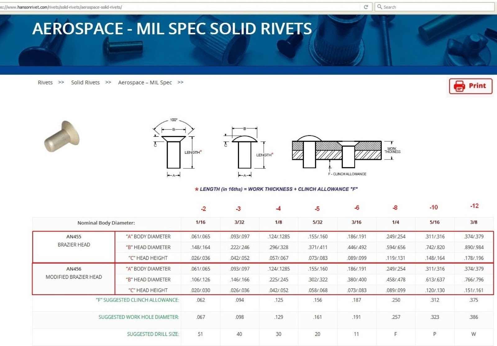
• Rivet head type:
The rivet on 2-2-V-1 is a "brazier" head. A brazier head rivet has a low profile, minimizing drag. There are two kinds of brazier head rivets,  the "full brazier head" and the "modified brazier head".  As early as 1930 and as late as 1941and possibly later, the "modified brazier head" was known as the "mushroom head."  The rivet on 2-2-V-1 is what is now known as a "full brazier head" rivet. Lockheed Electras had dimpled "full brazier head rivets" identical to the rivet on 2-2-V-1.  See photo below.


• Sheet thickness
The 2-2-V-1 sheet has a thickness of 0.032" - Source NTSB Laboratory


Tom saw these comments and in response wrote a detailed explanation of how various measurements he made were done. This additional information now appears in Tom’s report as Appendix II.

In this post, I’ll provide what I hope is a summary of Tom's Appendix II that will be helpful to layman like me out there who are following the 2-2-V-1 story. I’ll also provide additional information on how 2-2-V-1 appears to match the NEAM C-47 wing that Tom only became aware of after his report was published online.

The first bullet item is about rivet shaft diameter.  During Gillespie and Palshaw’s joint examination of the NEAM C-47 wing, Ric Gillespie questioned whether certain rivets were -4 rivets rather than -3 rivets. One of the main points Tom makes in his report is that the rivets in question are indeed -3 rivets. Appendix II of Tom’s report explains how  this was determined. Tom removed a rivet from the C-47 wing and inserted a drill that matched the rivet hole. This was a number 40 drill, the recommended drill size for -3 rivet holes. The matching drill for a -4 rivet hole is a number 30 drill, which does not fit into a -3 rivet hole. Tom provided a table from the Canadair Challenger Structural Repair Manual (1981), 51-42-11, page 6, figure 4, reproduced below, showing the correspondence between drill numbers and rivet hole sizes. Tom verified the -5 rivets on the C-47 wing using this same drill matching method.


Interested readers can check the photo below to see where Tom removed -3 rand -5 rivet removed from the C-47 wing to verify their sizes.

The second bullet item about rivet length states: “The rivet on 2-2-V-1 has a shaft length of 3/16 inch - source NTSB Laboratory.” I checked the NTSB report on TIGHAR’s web site [1] but see nothing there about rivet shaft length, so I will set this bullet item aside.

The third bullet item is about rivet material. Gillespie states:

“The rivet on 2-2-V-1 has a dimple in the center of the head, signifying it is made of A17ST alloy”

The photos included in Tom’s report aren’t sharp enough to show whether the rivet heads have dimples, so I asked Tom about the rivet heads, and he confirmed that they do in fact have dimples. He sent me the photo below of -3 rivets on the C-47 wing that demonstrates this to be the case. The ruler laid alongside the -3 rivets makes clear that the 1 inch pitch of the -3 rivets. Thus, in terms of the material type and rivet pitch the NEAM C-47 wing matches TIGHAR artifact 2-2-V-1.


The fourth bullet item about rivet head type states that the one -3 rivet still attached to 2-2-V-1 is a brazier head rivet. The Matching Characteristics section of Tom’s report states that the  C-47 wing -3 rivets are also brazier head rivets. Tom confirmed in an email exchange with me that that the C-47 wing -3 rivets are brazier head rivets, not modified brazier head rivets.  The table below indicates that -3 brazier head rivets and -3 modified brazier head rivets have quite different head diameters and so can be readily distinguished from one another based on their size. Readers can check the photo above against the table below to confirm that diameter of the -3 rivet heads on the C-47 wing are correct for -3 brazier head rivets, not modified brazier head rivets.


Gillespie’s fifth bullet item concerns sheet thickness.  The ALCLAD sheet that 2-2-V-1 is made of is 0.032 inches thick. The ‘What on Artifact 2-2-V-1 Matches the Wing of a C-47B?’ section of Tom’s report states that the thickness of the NEAM C-47 wing in the area of interest is also .032 inches. The excerpt below from Appendix II of Tom’s report states:

To determine the grip length it was necessary to first measure the skin thickness. This was done by using a micrometer at the edge of the skin. To measure the grip length a "calibrated" cleco was used to compare a known stack up of aluminum to that of the wing. The result was a skin thickness of 0.032" and a stringer thickness of 0.060". This is similar to the NTSB Report.

Some of this is a little over the head of a layman like me, but what’s clear is that Tom determined the 0.032 inch skin thickness of the NEAM C-47 wing skin in the area of interest by using a micrometer to measure the skin edge.  Note also that in the above excerpt Tom points out another matching point between the C-47 wing and 2-2-V-1: in both cases, the underlying stringer the skin is attached to was 0.060 inches thick.

That is my layman’s summary of Tom Palshaw’s Appendix II.

I also mentioned that after Tom’s report was published he realized that there was yet another way in which the C-47 wing and 2-2-V-1 match. This new information has to do with 2-2-V-1’s ‘Tab’ feature. A line of –5 rivet holes runs along one edge of 2-2-V-1, and a ‘Tab’ of material juts out from that same edge (see photos below).  At the far edge of the ‘Tab’ are what appear to be partial holes of another line of rivets. I sent Tom a close-up photo of the Tab with measuring tape laid over it (see photos below) that indicates a 1 5/16 inch spacing between 2-2-V-1’s line of -5 rivets and the rivet line at the far edge of the Tab. On the NEAM C-47 wing the line of -5 rivets that corresponds to the -5 rivet line on 2-2-v-1 has a line of -6 rivets running adjacent to it, separated by 1 5/16 inches (see photo below). Thus, the spacing between these two rivet lines on the C-47 wing matches the spacing of the rivet lines seen on 2-2-V-1's Tab. Tom thinks the partial rivet holes on the Tab’s edge are for size -6 rivets, but none of the holes is complete, so this is unclear.

2-2-V-1. The Tab is at the lower edge. The line of -5 rivet holes runs across the lower edge of 2-2-V1 and through the Tab

Spacing between rivet hole lines on the Tab

Spacing between -5 and -6 rivet hole lines on the NEAM C-47


Ric Gillespie's remark that the C-47 wing is "not even close" to a match for 2-2-V-1, as he put it, just does not seem to hold up, given what Tom Palshaw has reported.  If clearer documentation of the C-47 wing's features are needed, I think Ric Gillespie knows how to obtain it.

Comments, corrections, additional relevant facts, differing viewpoints, etc., are always welcome.  Send to gardnersghost@gmail.com
+++
References
[1] https://tighar.org/Projects/Earhart/Archives/Documents/NTSB_Report/ntsbreport.html

Wednesday, December 4, 2019

Is 2-2-V-1 a Piece of the Sydney Island C-47 Wreck? An Update.


Two days ago I published a short post on Tom Palshaw’s report matching TIGHAR artifact 2-2-V-1 to the upper section of the wing of a C-47 in storage at the New England Air Museum (NEAM). Ric Gillespie had recently stated on the TIGHAR Forum that he had examined the NEAM C-47 wing and found it to be “not even close” to a match to 2-2-V-1, but he offered no specifics to back up this assessment.  I thought Tom had made a good case for 2-2-V-1 being a scavenged piece of the Sydney C-47 worthy of a more substantive response than Ric Gillespie had given it.

A TIGHAR forum member alerted Ric Gillespie to Tom’s online report, and possibly for this reason Gillespie posted a video of his examination of the NEAM C-47 wing back in 2017 on TIGHAR’s YouTube channel [1]. Tom participated in this examination, and the photo below shows Tom and Ric standing alongside the subject C-47 wing at the start of their joint examination.


The photo below shows 2-2-V-1 laid over the C-47 wing at the location of interest. The spacing between five rivet hole lines on the side of 2-2-V-1 closest to the camera matches the rivet line spacing of the underlying C-47 wing quite well. There isn’t a good view in the video showing how closely the rivet hole lines match at other side of 2-2-V-1, but I think it is pretty clear that the alignment is close on that side as well, because nowhere in the video does Ric or Tom say that 2-2-V-1’s rivet line spacings don’t match those of the C-47 wing. So in terms of spacing of rivet hole lines, 2-2-V-1 seems to match up well with Tom’s candidate C-47 wing.


So in what ways might 2-2-V-1 not match a C-47 wing, if not rivet line spacing? Ric offers three primary objections to Tom’s proposed match, which if I understand them correctly are as follows:

  • One line of rivets on the C-47 wing are the wrong sized rivets, i.e., -4 rivets rather than -3 rivets
  • The line of -5 rivets of the C-47 lacks the irregular spacing between 2-2-V-1’s row of -5 rivet holes (these are the rivet holes along the right edge of 2-2-V-1 in the above photo
  • A straight portion of what is the far edge of 2-2-V-1 in the above photo is thought to represent a fatigue failure caused by repetitive bending against a straight object. Ric argues this straight object must an underlying structural component, but no such structural component exists where Ric argues it would need to be.
In the TIGHAR YouTube video, Tom appears to accept Ric’s three objections. However in the days after Ric’s visit, Tom examined the C-47 wing more closely and found reasons to think that he had been too hasty in accepting Ric’s objections:
  • Tom found that the line of rivets Ric thought to be -4 rivets (too big) were actually -3 rivets (matching 2-2-V-1)
  • Tom found that there were irregularities in spacing between -5 rivets, just as on 2-2-V-1
  • In Tom’s opinion, Ric’s hypothesis for the formation 2-2-V-1 straight-edge failure feature was not the only way the straight edge could have been created. Tom suggested instead that “2-2-V-1 was originally larger when removed from the source aircraft. A piece could then have been removed later by placing the artifact between two straight angles and flexed to failure”
All of these points were made by Tom in an email Tom sent Ric Gillespie a few days after the NEAM visit in 2017. That email differs only in small ways from Tom’s online report. My understanding is that Ric Gillespie has never responded to Tom’s email.

All this makes it very hard for me to understand how Ric Gillespie could have recently said that the C-47 wing he and Tom examined is not even close to a match for 2-2-V-1. I can only conclude from the information available to me that Tom Palshaw has found a plausible candidate source for 2-2-V-1, and not only because of the many ways in which the features match, but also because the people of Gardner Island used scavenged aluminum from the Sydney Island C-47 wreck for making handicrafts [2].

I suspect this  post will be followed by several more update posts.

Comments, corrections, additional relevant facts, differing viewpoints, etc., are always welcome.  Send to gardnersghost@gmail.com
++++
References

[1] https://www.youtube.com/watch?v=GlVLyOfsZ3c

[2] Earhart Research Bulletin #7, 7/26/98. Accessible at:
https://tighar.org/Projects/Earhart/Archives/Research/Bulletins/07_Sydneycrash/07_Sydneycrash.html

Sunday, November 24, 2019

Is 2-2-V-1 a Piece of the Sydney Island C-47 Wreck?

Since 1992 TIGHAR has argued that piece of aluminum sheet it refers to as artifact 2-2-V-1 found during a TIGHAR expedition to Nikumaroro is a piece of Amelia Earhart's Lockheed Model 10 Electra [1]. TIGHAR's initial case for 2-2-V-1 was that it was a piece of the underbelly of the Electra was quickly debunked. But Ric Gillepsie, TIGHAR's leader, is nothing if not persistent, and so TIGHAR continued over the years to try to find a way to fit 2-2-V-1 onto Earhart's Electra. Many of the key points Gillespie has put forward over the years for 2-2-V-1 being a piece of the Electra have turned out to indicate the opposite but Gillespie simply continues to march forward, steadfastly ignoring or downplaying evidence that goes against his preferred conclusion.

The long history of TIGHAR's claims about 2-2-V-1 is something that I've been wanting to  post about because I think it illustrates problems that arise all too often with TIGHAR's promotion of the Nikumaroro Hypothesis (Gillespie would of course say that he is testing the Nikumaroro Hypothesis, not promoting it, but come on...).  Anyone who scrolls back through my blog posts can see that I'm not exactly a prolific generator of new material. So while my epic blog post series on 2-2-V-1 awaits fruition I'd like to point readers to a report by Tom Palshaw, who works on aircraft restoration projects at the New England Air Museum in Connecticut.  It is pretty clear that 2-2-V-1 isn't from Earhart's Electra, but then what airplane is it from? Tom has suggested a possible answer: he has found that rivet line spacings, rivet types, and aluminum ‘skin’ thickness of artifact 2-2-V-1 match a section of the upper  wing of a C-47 in NEAM's collection.  C-47s were workhorse U.S. military transport planes during World War Two, and significantly, a C-47 crashed on Sydney Island, another island in the Phoenix Island group, during the war [2].  According to TIGHAR, pieces of that  C-47 were brought to Nikumaroro for use by local inhabitants in making items such as combs.

I helped Tom create an online a report of his findings, which can be found here.

I'm certainly no expert on aircraft manufacture but it seems to me that Tom Palshaw has made a good case that 2-2-V-1 is a piece of aluminum recovered from the Sydney Island crash. It also seems to me that the substance of Tom's findings should be better known by TIGHAR's followers than they probably are. Tom informed Ric Gillespie of this putative match back in 2017, but for two years TIGHAR said nothing about Tom's findings on the TIGHAR discussion forum or its Facebook page.  That silence was only broken this summer when Gillespie made the following tersely worded post on TIGHAR forum [3]:

"On July 16, 2017 I inspected the portion of the DC-3/C-47 wing section at the New England Air Museum alleged to resemble Artifact 2-2-V-1. At the time the wing section was out behind the museum, stored outdoors with various other bits and piece of aircraft. There was no way to check the thickness of the skin but, although there were some general similarities in rivet pattern, the rivet type, rivet pitch, and spacing between rivet lines did not match the artifact. Not even close. TIGHAR videographer Mark Smith recorded the investigation."

Gillespie doesn't provide TIGHAR forum members with Tom Palshaw's side of the story although by this time Gillespie had long since received by email from Tom an analysis that is not much different from the online report I've linked to above. Gillespie could simply have quoted from Tom's email or provided a summary of Tom's key points in his post.  Tom sent Ric a photo showing how a template of 2-2-V-1 matches up with the NEAM C-47 wing (see below), and the match looks pretty good to me, certainly close enough to wonder why Gillespie could have made his 'not even close' comment.


Given all the ink that has been spilled about 2-2-V-1 by Ric Gillespie, it strikes me that Tom Palshaw's findings deserve a serious reply from Gillespie. It could be that Gillespie is correct that C-47 wing is 'not even close', but it isn't enough for Gillespie to simply say it, he needs to explain why that is so. 


+++
References
[1] See TIGHAR TRACKS, Vol. 8 No. 1/2, article titled 'WE DID IT'. Accessible at:  https://tighar.org/Publications/TTracks/1992Vol_8/0801_2.pdf
[2] See TIGHAR Earhart Research Bulletin #7, 7/26/98. Accessible at:
https://tighar.org/Projects/Earhart/Archives/Research/Bulletins/07_Sydneycrash/07_Sydneycrash.html
[3] See TIGHAR forum thread titled 'RE: 2-2-V-1 Wing Panel Comparisons', post #2. Accessible at:  https://tighar.org/smf/index.php/topic,2074.msg43099.html#msg43099

Note: I originally learned about Tom Palshaw's findings from a post made on the Aviation Mysteries forum. I would link to that post here if I could find it. The post was made long ago and is now buried somewhere deep within the discussion threads there.